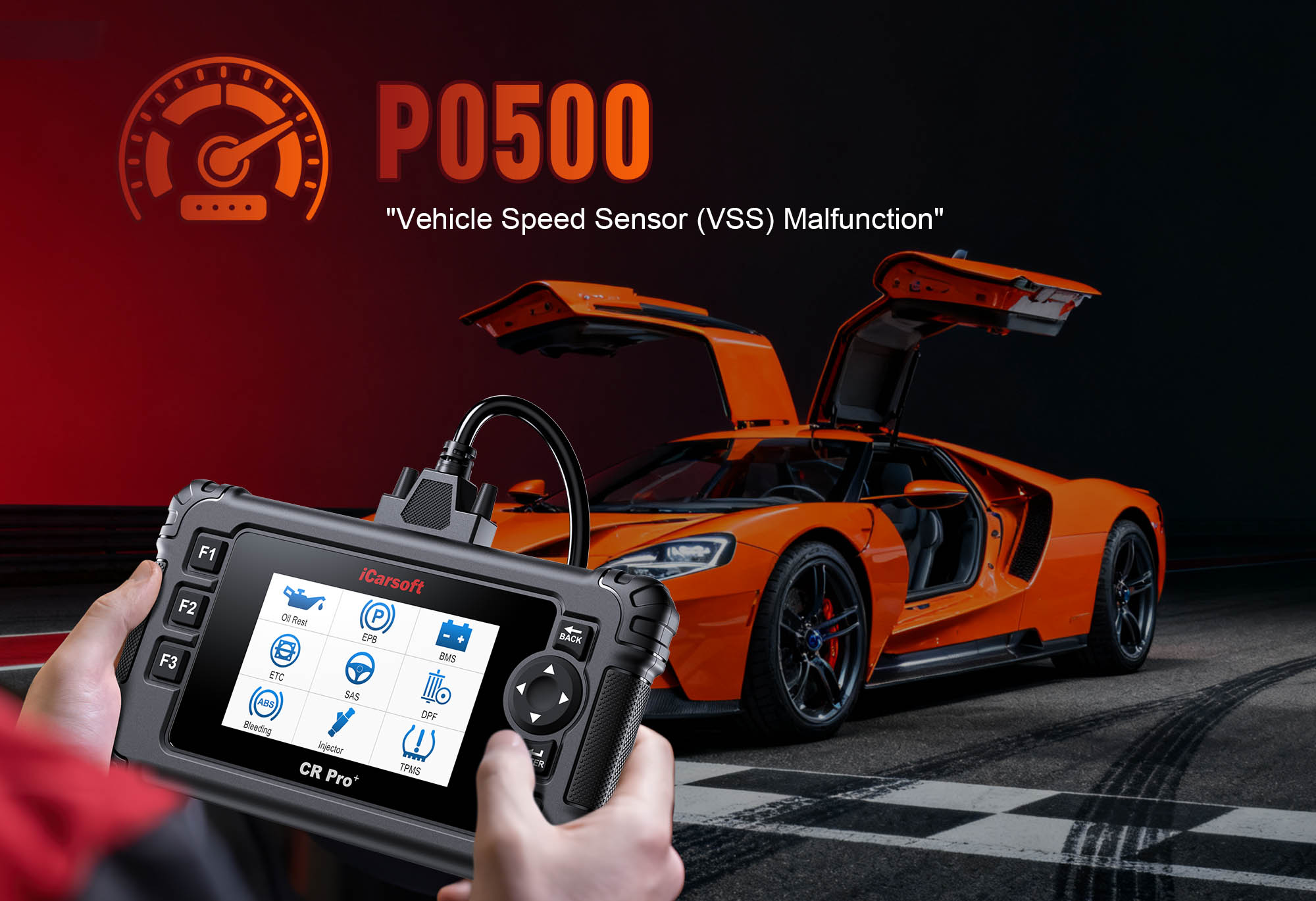
Diagnose & Clear P0500 with iCarsoft CR Pro+: Fix Vehicle Speed Sensor Malfunction
If your check engine light illuminates and a scan returns P0500, your vehicle’s speed monitoring system is signaling a critical failure. This generic OBD-II code stands for "Vehicle Speed Sensor (VSS) Malfunction"—indicating the Engine Control Module (ECM) is receiving erratic, weak, or no signal from the vehicle speed sensor, preventing accurate speed tracking.
The vehicle speed sensor measures how fast your vehicle is moving and sends this data to multiple systems: the ECM (for adjusting fuel injection and ignition timing), the anti-lock braking system (ABS) (for traction control), the transmission control module (TCM) (for shift points), and the instrument cluster (for the speedometer). When P0500 occurs, this data stream is disrupted, leading to a cascade of issues from inoperable speedometers to transmission shifting problems.
Basic scanners might only confirm "speed sensor fault" but can’t test sensor signal strength or isolate issues to wiring vs. the sensor itself. The iCarsoft CR Pro+—with its real-time speed sensor data, circuit testing, and component activation tools—solves this. Let’s walk through how to diagnose and resolve P0500.
 iCarsoft CR Pro+ monitoring VSS signal frequency and calculated speed for P0500 diagnosis
Understanding P0500: Causes & Key Symptoms
To tackle P0500 effectively, recognize how a faulty VSS disrupts critical vehicle systems:
Key Symptoms of P0500
-
Check Engine Light: Illuminates when the ECM detects no valid speed signal for 5+ seconds of driving (even at low speeds).
-
Inoperable Speedometer: The gauge stays at 0 mph/kph or fluctuates randomly, even when the vehicle is moving.
-
Transmission Issues: Automatic transmissions may shift erratically (e.g., hard shifts, delayed shifts), stay in one gear, or enter "limp mode" (caps speed at 40–50 mph to avoid damage).
-
ABS/Traction Control Warnings: These systems rely on speed data—missing signals trigger their dashboard warning lights.
-
Cruise Control Failure: Cruise control won’t engage, or disables unexpectedly, due to missing speed feedback.
-
Poor Fuel Economy: The ECM can’t adjust fuel delivery based on speed (e.g., too much fuel at highway speeds), leading to 5–10% higher fuel consumption.
Common Causes of P0500
|
Cause
|
Description
|
|
Faulty Vehicle Speed Sensor (VSS)
|
Internal electrical failure (worn magnets, broken wiring, or failed Hall effect chip) stops the sensor from generating a signal (accounts for ~40% of P0500 cases).
|
|
Damaged VSS Wiring
|
Frayed, cut, or corroded wires between the VSS and ECM/TCM disrupt signal transmission—common near moving parts (transmission shafts) or undercarriages (road debris damage).
|
|
Loose or Contaminated Connector
|
Dirt, moisture, or corrosion in the VSS connector creates a weak electrical connection—worse for wheel speed sensors (WSS) exposed to road spray.
|
|
Reluctor Ring Issues (Magnetic VSS)
|
The toothed reluctor ring (mounted near the VSS) has missing/broken teeth or rust buildup, preventing the sensor from detecting rotation.
|
|
Instrument Cluster Malfunction
|
A faulty cluster fails to display speed even if the VSS works (rare—confirmed via scanner’s "Calculated Vehicle Speed" reading).
|
|
ECM/TCM Error (Rare)
|
Software glitches or hardware failure in the control module prevent it from processing the VSS signal—usually paired with other communication codes (e.g., P0606).
|
Why iCarsoft CR Pro+ Excels at Diagnosing P0500
The CR Pro+ outperforms basic tools with features tailored to speed sensor and multi-system diagnostics—critical for pinpointing P0500’s root cause:
Dual Speed Signal Monitoring
Displays both the VSS raw signal (frequency in Hz for magnetic; digital pulses for Hall effect) and the ECM’s interpreted speed (mph/kph), highlighting mismatches (e.g., signal present but speed = 0 = module fault).
Circuit Continuity & Resistance Testing
Identifies breaks, shorts, or high-resistance issues in VSS wiring, eliminating guesswork about electrical faults (e.g., broken wire vs. corroded connector).
Sensor Signal Validation
Generates test signals to verify if the ECM/TCM can receive speed data—rules out module faults without replacing expensive components.
Vehicle-Specific VSS Diagrams
Preloaded with color-coded schematics showing VSS locations (transmission output shaft, wheel hub, differential) and wiring paths for 65+ makes (e.g., Hyundai Sonata, Dodge Ram, BMW 3 Series).
Reluctor Ring Inspection Guides
Provides step-by-step instructions to check the reluctor ring (teeth condition, alignment) for magnetic VSS designs—avoids missing hidden mechanical issues.
Multi-System Integration Tests
Checks communication between the VSS, ECM, TCM, ABS, and instrument cluster to isolate where the signal fails (e.g., VSS works but cluster doesn’t = cluster fault).
Step-by-Step: Diagnose P0500 with iCarsoft CR Pro+
-
1. Connect & Confirm the Code
Plug the CR Pro+ into your vehicle’s OBD-II port (under the dashboard) and power it on.
Select your vehicle via Auto VIN Scan (reads your VIN in 2 seconds) or manual entry (make/model/year/transmission type: automatic/manual).
Navigate to Engine > Fault Codes > Read Codes to confirm P0500. Tap Code Details for vehicle-specific info (e.g., "BMW: Vehicle Speed Sensor Signal Missing – Check Transmission Output Sensor").
-
2. Identify VSS Type & Location
First, determine your VSS type and mounting point using the CR Pro+:
VSS Type Identification:
Navigate to Component Location > Transmission > Sensors > Vehicle Speed Sensor.
The scanner categorizes your VSS as one of three types:
- Magnetic: Uses a reluctor ring (toothed wheel) and generates AC voltage (common in pre-2000 vehicles).
- Hall Effect: Electronic sensor with digital 0V/5V pulses (standard in 2000+ vehicles).
- Wheel Speed Sensor (WSS)-Based: No dedicated VSS—ABS wheel sensors calculate speed (e.g., modern FWD vehicles).
VSS Location:
- Magnetic/Hall Effect: Typically mounted on the transmission output shaft (rear of transmission) or differential (RWD vehicles).
- WSS-Based: Integrated into front/rear wheel hubs (look for sensors with 2–3 pin connectors near brake calipers).
-
3. Monitor Real-Time Speed Data
Verify the missing/erratic signal with the CR Pro+’s live data (requires a helper to drive):
Have a helper start the engine and slowly drive the vehicle (10–20 mph) in a safe area while you monitor the scanner.
Navigate to Engine > Live Data > Vehicle Speed and select these parameters:
- "VSS Signal Frequency" (magnetic: 50–500 Hz; Hall effect: digital pulse count).
- "Calculated Vehicle Speed" (ECM’s interpretation of the VSS signal, in mph/kph).
- "Speedometer Output" (signal sent to the instrument cluster).
P0500 Confirmation Scenarios:
- No Signal: Frequency = 0 Hz and calculated speed = 0 mph while moving = VSS or wiring fault.
- Erratic Signal: Frequency/speed jumps randomly (e.g., 5 mph to 30 mph) = loose connector or damaged wiring.
- Signal Present, No Speed Display: Frequency normal but speedometer output = 0 = instrument cluster fault.
-
4. Inspect VSS Connector & Wiring
Poor connections are a top cause of P0500—inspect with the CR Pro+’s guidance:
Turn off the engine and disconnect the negative battery terminal (prevents electrical shorts during testing).
Connector Inspection:
Locate the VSS connector (use the scanner’s diagram) and disconnect it (press the locking tab or remove the clip). Check for:
- Corrosion (white/green powdery deposits) on terminals (common in WSS connectors exposed to road salt).
- Bent, broken, or pushed-in pins (from improper disconnection).
- Moisture or dirt inside the connector (sign of water intrusion).
Clean corroded terminals with electrical contact cleaner and a small brush; straighten bent pins carefully with a needle-nose plier.
Wiring Inspection:
Follow the VSS wiring from the connector to the ECM/TCM (use the CR Pro+’s wiring schematic). Look for:
- Frayed or cut insulation (near moving parts like transmission shafts or wheel bearings).
- Rodent damage (chewed wires in the engine bay or undercarriage).
- Pinched wires (from loose harness clips rubbing against metal components).
Mark damaged sections for repair; replace wiring with automotive-grade, heat-resistant wire if insulation is severely compromised.
-
5. Test VSS Circuit Continuity & Resistance
Use the CR Pro+ to rule out wiring faults:
Continuity Test (Signal Path):
Navigate to Special Functions > Electrical Tests > Circuit Continuity.
Connect one test lead to the VSS signal pin (labeled "SIG" in the connector diagram) and the other to the corresponding ECM/TCM pin (found in the scanner’s wiring schematic).
- Normal: 0–1 ohm resistance (signal path is clear).
- Faulty: Infinite resistance = broken wire (repair with heat-shrink butt connectors or replace the harness section).
Short Circuit Test (Ground Path):
Select Special Functions > Electrical Tests > Short Circuit Test.
Connect one lead to the VSS signal wire and the other to the vehicle’s chassis (clean a ground point with sandpaper first).
- Normal: >100 ohms (no short).
- Faulty: <5 ohms = short to ground (repair damaged insulation where the wire touches metal).
-
6. Test the VSS for Internal Failure
If wiring and connections are intact, test the VSS itself with the CR Pro+:
Magnetic VSS Test:
1. Disconnect the VSS from its connector and remove the sensor (use a socket wrench—follow the scanner’s safety tips to avoid dropping parts into the transmission).
2. Connect the CR Pro+’s test leads to the VSS terminals (match "SIG" to signal, "GND" to ground).
3. Spin the VSS’s tip with a drill (low speed, ~500 RPM) to simulate rotation.
- Normal: Scanner displays AC voltage (0.5–5V, increasing with drill speed) = sensor works.
- Faulty: No voltage = replace the VSS.
Hall Effect/WSS Test:
1. Reconnect the battery but leave the VSS connector disconnected.
2. Back-probe the connector (insert test leads into the back of the connector without damaging pins) to access the signal and ground pins.
3. Have a helper rotate the wheel (for WSS) or transmission output shaft (for Hall effect VSS) by hand.
- Normal: Scanner shows digital pulses (0V to 5V alternating) = sensor works.
- Faulty: No pulses or steady voltage = replace the VSS.
-
7. Check Reluctor Ring (For Magnetic VSS)
A damaged reluctor ring disrupts magnetic VSS signals—inspect with the CR Pro+:
1. Locate the reluctor ring using the scanner’s diagram (mounted on the transmission output shaft or differential, near the VSS mounting hole).
2. Visually inspect the ring for:
- Missing, broken, or bent teeth (common from impact with road debris).
- Rust or debris buildup (blocks the magnetic signal).
3. Clean light rust with a wire brush; for heavy rust or damaged teeth, replace the ring.
Note: Reluctor ring replacement may require partial transmission/differential disassembly. If you’re not experienced, consult a mechanic—incorrect installation damages the transmission.
-
8. Verify Multi-System Communication
Rule out faults in the ECM, TCM, or instrument cluster with the CR Pro+:
Instrument Cluster Test:
Navigate to Special Functions > Body > Instrument Cluster > Speedo Test.
The scanner sends a test signal to the cluster— the speedometer should move to 60 mph/kph and hold steady = cluster works. No movement = replace the cluster.
ECM/TCM Signal Reception Test:
Go to Special Functions > ECM > Signal Simulation and select "Vehicle Speed".
Input a test speed (30 mph/kph) and confirm the ECM/TCM acknowledges it (scanner shows "Signal Received" = module works). No acknowledgment = ECM/TCM issue (consult a professional for reprogramming or repair).
-
9. Repair & Clear P0500
Fix the root cause based on diagnostics—prioritize low-cost, easy repairs first:
- Faulty VSS: Replace with an OEM sensor (use the CR Pro+’s Part Lookup for compatibility—e.g., Denso 28164-22010 for Toyota, ACDelco 213-4689 for GM).
- Damaged Wiring: Repair with heat-shrink butt connectors (use 18-gauge wire for signal paths); replace severely corroded harness sections.
- Corroded Connector: Clean terminals with contact cleaner or replace the connector. Apply dielectric grease to WSS connectors (critical for moisture resistance).
- Damaged Reluctor Ring: Replace the ring (if accessible) or have a mechanic perform the repair for transmission-mounted rings.
Clear the Code: Navigate to Engine > Fault Codes > Clear Codes to delete P0500 and any related ABS/transmission faults.
-
10. Validate the Repair
Confirm the VSS and speed monitoring system work correctly to avoid P0500 recurrence:
Road Test: Drive the vehicle at 20–60 mph/kph on a flat road. Use a GPS app (e.g., Google Maps) to compare actual speed to the speedometer—readings should match within 2 mph/kph.
Live Data Verification: Monitor VSS frequency and calculated speed during the drive—both should rise smoothly with acceleration and drop steadily with deceleration (no jumps or drops).
System Checks: Verify transmission shifts normally (no hard/late shifts), cruise control engages/disengages, and ABS/traction control warning lights stay off.
Re-Scan: Plug the CR Pro+ back in and run a fault code scan—no P0500 recurrence + all systems functioning = successful repair.
Preventing P0500 Recurrence
The CR Pro+ helps maintain reliable speed monitoring long-term, avoiding future P0500 issues:
-
VSS Maintenance: Use the CR Pro+’s Service Reminder to inspect the VSS every 60,000 miles. Check for oil leaks (transmission oil damages VSS) and clean WSS connectors annually.
-
Wiring Protection: Secure loose wire harnesses away from moving parts (transmission shafts, wheel bearings) with zip ties. Use loom tape to protect exposed wiring under the vehicle.
-
Connector Care: Apply dielectric grease to all VSS/WSS connectors—repels moisture and prevents corrosion (critical for vehicles driven in snow/salt or rainy climates).
-
Reluctor Ring Inspection: Check the ring for debris during transmission fluid changes. Clean light rust with a wire brush to avoid signal interference.
-
Extreme Weather Prep: In snowy climates, clear ice from wheel speed sensors before driving—frozen ice blocks the sensor’s signal, causing temporary P0500.
-
Transmission Maintenance: Change transmission fluid per the manufacturer’s schedule (usually every 30,000–60,000 miles)—old fluid can damage transmission-mounted VSS.
Conclusion
P0500’s VSS malfunction disrupts critical vehicle systems—from speedometers to transmissions—making safe driving and maintenance challenging. The iCarsoft CR Pro+ simplifies diagnosis by cutting through guesswork: it distinguishes sensor faults from wiring issues, verifies multi-system communication, and ensures repairs target the root cause.
Whether you’re replacing a faulty VSS, repairing damaged wiring, or cleaning a corroded connector, the CR Pro+ provides the real-time data and vehicle-specific guides needed to restore accurate speed monitoring. With this guide, you’ll turn a "vehicle speed sensor malfunction" into a confident repair—keeping your speedometer, transmission, and safety systems working in perfect harmony for miles to come.
FAQs About P0500 Code
Q: Can I drive my vehicle with P0500?
A: Drive cautiously and only for short trips. P0500 disables the speedometer (making it hard to avoid speeding/tickets) and can trigger transmission limp mode. Avoid highway driving or towing—undetected speed changes increase accident risk, and transmission stress may cause permanent damage.
Q: How much does it cost to fix P0500?
A: Costs vary by cause: OEM VSS = $30–$150 (DIY); wiring repair = $10–$50 (DIY); reluctor ring replacement = $100–$300 (professional, due to transmission disassembly); cluster replacement = $200–$500 (professional). The CR Pro+ saves money by avoiding unnecessary module replacements.
Q: Why does P0500 come back after replacing the VSS?
A: Common reasons: 1) Unrepaired wiring fault (e.g., broken wire still disrupts signal); 2) Reluctor ring damage (magnetic VSS only); 3) Wrong sensor (aftermarket VSS doesn’t match OEM signal specs); 4) ECM/TCM needs reprogramming. Re-run the CR Pro+’s circuit and reluctor tests to find leftover issues.
Q: How do I know if my vehicle uses a wheel speed sensor (WSS) instead of a dedicated VSS?
A: Use the CR Pro+’s Component Location tool: if "Vehicle Speed Sensor" redirects to "Wheel Speed Sensors" (under ABS), your vehicle uses WSS for speed data. You’ll also see ABS warning lights alongside P0500, as the systems share sensors.
Q: Can a dead battery cause P0500?
A: No, but a weak battery (voltage <12V) can cause intermittent P0500. The VSS requires stable voltage to generate a consistent signal—low battery power leads to erratic signals. Test the battery with the CR Pro+’s Battery Test function (under Special Functions > Electrical Tests); replace if voltage is low, then clear the code and re-test.