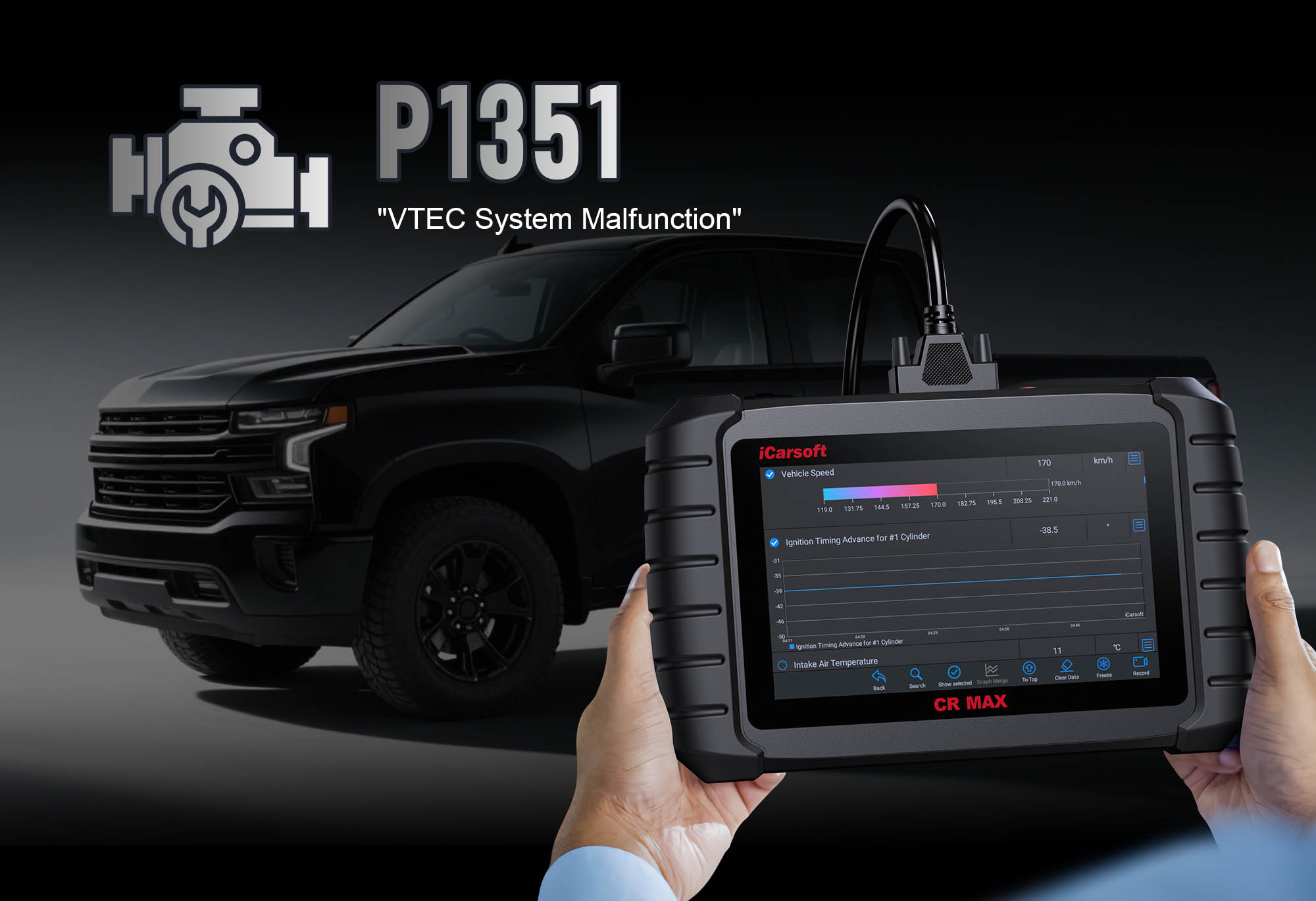
Diagnose & Clear P1351 with iCarsoft CR MAX: Fix Ignition Coil Control Circuit Issues
If your check engine light illuminates and a scan returns P1351, your vehicle is signaling a problem with its ignition system. This manufacturer-specific code—common in GM, Ford, and Chrysler vehicles—typically indicates an "Ignition Coil Control Circuit High Voltage (Bank 1, Cylinder 1)" or a similar issue with the ignition coil driver circuit.
The ignition coil converts low-voltage battery power into the high voltage needed to ignite fuel in the combustion chamber. Modern systems use coil-on-plug or coil packs controlled by the Engine Control Module (ECM), which sends precise timing signals to trigger spark. When P1351 occurs, the ECM detects abnormally high voltage in the control circuit for Bank 1, Cylinder 1’s coil, disrupting spark timing and causing misfires, reduced power, or even stalling.
Basic scanners might only flag "ignition coil fault" but can’t isolate whether the issue is a faulty coil, damaged wiring, or a failing ECM driver. The iCarsoft CR MAX solves this with vehicle-specific ignition system diagrams, real-time coil voltage monitoring, and active circuit tests. Let’s walk through how to diagnose and resolve P1351.
Why It Matters
Ignoring P1351 risks more than just a lit check engine light—it undermines your engine’s performance and risks expensive damage. The ignition coil’s role in spark generation is critical: a disrupted control circuit for Cylinder 1 leads to incomplete combustion, wasted fuel, and increased emissions. Over time, unburned fuel can overheat the catalytic converter (costing $800–$1,500 to replace) and cause premature wear on spark plugs, pistons, and valves.
In severe cases, P1351 can cause persistent misfires that make the engine undriveable. Addressing it promptly with the iCarsoft CR MAX not only restores smooth operation but also prevents cascading failures that drain your wallet.
Understanding P1351: Causes & Key Symptoms
To diagnose P1351 effectively, first break down the ignition coil control system and its failure triggers:
Key Symptoms of P1351
-
Illuminated Check Engine Light: The primary indicator—activates when the ECM detects control circuit voltage exceeding 10V for 3+ consecutive seconds.
-
Engine Misfire: Notable misfire in Cylinder 1, felt as rough idle, shaking during acceleration, or hesitation under load.
-
Reduced Power & Performance: Noticeable loss of acceleration, especially at low RPMs where ignition timing is most critical.
-
Increased Fuel Consumption: Unburned fuel from misfires leads to 10–15% worse fuel economy.
-
Catalytic Converter Risk: Unburned hydrocarbons (HC) overheat the catalytic converter, potentially causing it to melt or fail.
Common Causes of P1351
|
Cause
|
Description
|
|
Faulty Ignition Coil
|
Internal short in the coil’s primary winding causes high voltage feedback to the ECM—most common cause of P1351.
|
|
Wiring Issues
|
Damaged insulation, short circuits to power, or corroded connections in the coil’s control circuit (often from oil leaks or heat exposure).
|
|
Failed ECM Driver
|
The ECM’s internal transistor controlling the coil fails, causing voltage spikes or an open circuit—requires professional ECM repair/replacement.
|
|
Loose Connections
|
Poor contact in the coil’s electrical connector increases resistance, leading to voltage fluctuations detected by the ECM.
|
|
Ground Problems
|
Corroded or loose ground wires for the ignition system disrupt proper voltage return paths, causing false high-voltage readings.
|
Why iCarsoft CR MAX Excels at Diagnosing P1351
Basic OBD-II scanners can’t decode P1351’s make-specific nuances, but the iCarsoft CR MAX is tailored to GM, Ford, and Chrysler ignition systems:
Vehicle-Specific Ignition Data
Preloaded with coil locations (Bank 1, Cylinder 1), wiring diagrams, and voltage specs for GM Silverado, Ford F-150, Chrysler 300, and more.
Real-Time Coil Voltage Monitoring
Displays live control circuit voltage (normal: 0V–12V pulses) to spot sustained high voltage (>10V) that indicates shorts or driver issues.
Ignition Coil Activation Tests
Manually triggers the coil to measure current draw (typically 4–8A) and voltage response—confirms coil vs. wiring issues.
Cylinder Balance Tests
Identifies misfires by comparing RPM drops across cylinders—isolates Cylinder 1 as the source of P1351.
Component Location Guides
Shows exact position of Bank 1, Cylinder 1 coil (e.g., front-left on GM V8s, driver’s side on Ford inline-4s).
Auto VIN Detection
Automatically identifies engine configuration (V6/V8/inline) to ensure accurate cylinder numbering—eliminates guesswork.
Step-by-Step: Diagnose P1351 with iCarsoft CR MAX
-
1. Connect & Confirm the Code
Plug the CR MAX into your vehicle’s OBD-II port (under the dashboard) and power it on. Select your vehicle via Auto VIN (fast and accurate) or manual entry (make/model/year). Navigate to Engine > Fault Codes > Read Codes to confirm P1351. Tap Code Details for vehicle-specific insights (e.g., "GM: Ignition Coil 1 Control Circuit Voltage High" or "Ford: Cylinder 1 Coil Driver Circuit Open").
-
2. Check for Related Codes
P1351 rarely appears alone—scan for companion faults to narrow the root cause:
- P0300: Random/Multiple Cylinder Misfires
- P0301: Cylinder 1 Misfire Detected
- P1350/P1352: Other Ignition Coil Circuit Faults (e.g., Cylinder 2, 3)
- P0607: ECM Internal Control Module Performance
Address these first—multiple codes often indicate a shared issue (e.g., bad ground or ECM problem).
-
3. Locate Bank 1, Cylinder 1 Ignition Coil
Use the CR MAX’s Component Location tool to identify Bank 1 (usually the cylinder bank containing cylinder #1; check diagrams for your engine):
- GM V8: Bank 1 is driver’s side (left)
- Ford V6: Bank 1 is passenger’s side (right) for some models
- Chrysler Inline-4: Bank 1 is the only bank
Locate Cylinder 1’s coil: Coil-on-plug systems have individual coils; coil packs have a shared unit with labeled terminals (e.g., "C1" for Cylinder 1).
-
4. Monitor Live Ignition Data
Use the CR MAX’s real-time data to spot voltage irregularities:
1. Go to Engine > Live Data > Ignition System and select:
- "Ignition Coil 1 Control Voltage" (should pulse between 0V–12V as the ECM triggers the coil)
- "Cylinder 1 Misfire Count" (increases with P1351-related misfires)
2. Start the engine and observe:
- Sustained voltage >10V = short in coil or wiring
- No voltage pulse = broken wire or ECM driver failure
- High misfire count = confirmed Cylinder 1 ignition issue
-
5. Inspect the Coil & Wiring
Visually examine the ignition coil and its harness for physical damage:
- Coil Body: Look for cracks, oil contamination (sign of leaking valve cover gasket), or burn marks (indicates overheating).
- Electrical Connector: Inspect for green/white corrosion, bent pins, or loose terminals—clean corroded connectors with electrical contact cleaner.
- Wiring Harness: Check for frayed insulation, cuts, or damage where the harness rubs against engine components (e.g., exhaust manifolds).
-
6. Test the Ignition Coil
Use the CR MAX to run targeted resistance tests on the coil:
1. Navigate to Special Functions > Engine > Ignition Tests > Coil Resistance Test
2. Select "Cylinder 1" and follow prompts to measure:
- Primary Resistance: Normal range: 0.5–2.0Ω (varies by make/model—consult CR MAX’s specs)
- Secondary Resistance: Normal range: 8,000–15,000Ω
3. Result: Readings outside specs = faulty coil
4. Swap Test (If Safe): Swap Cylinder 1’s coil with another cylinder (e.g., Cylinder 2) using the CR MAX’s diagram. Rescan: P1350/P1352 appears = faulty coil (replace it); code remains = wiring/ECM issue.
-
7. Test the Control Circuit
Wiring issues often mimic coil failures—use the CR MAX to verify circuit integrity:
1. Go to Special Functions > Engine > Circuit Tests > Ignition Coil Control Circuit
2. Test for:
- Short to Power: Unexpected 12V when coil is inactive (indicates wiring touching power source)
- Open Circuit: No continuity between coil and ECM (broken wire)
- Ground Integrity: Resistance <0.5Ω (high resistance = corroded ground)
3. Fixes: Repair frayed wires with heat-shrink connectors; replace severely damaged harnesses; clean/re-tighten ground connections.
-
8. Check for ECM Issues
If coil and wiring test good, the ECM’s driver circuit may be faulty:
1. Use the CR MAX’s ECM Communication Test to verify the module receives/sends signals properly.
2. Check for technical service bulletins (TSBs) via the CR MAX’s Service Info—some manufacturers offer ECM reflashes for P1351-related software bugs.
3. Professional Help: If tests indicate ECM failure, consult a shop for reflashing or replacement (OEM ECMs cost $300–$800, plus programming).
-
9. Repair & Clear P1351
Fix the root cause based on diagnostics:
- Faulty Coil: Use the CR MAX’s Part Lookup to find OEM coils (e.g., AC Delco D510C for GM, Motorcraft DG511 for Ford).
- Wiring/Connectors: Repair as noted in Step 7; apply dielectric grease to connectors to prevent future corrosion.
- ECM Issues: Have the ECM reflashed or replaced by a professional.
Clear the code: Navigate to Engine > Fault Codes > Clear Codes to delete P1351.
-
10. Verify the Repair
Take a 15-minute test drive, including:
- Idle periods to check for smooth operation
- Acceleration tests to monitor for hesitation/misfires
- Highway driving to ensure consistent performance
Use the CR MAX’s Data Logging to record coil voltage and misfire counts during the drive. Re-scan after: No return of P1351 + zero misfires = successful repair; code return = revisit coil/wiring tests or ECM diagnostics.
Preventing P1351 Recurrence
Use the iCarsoft CR MAX to maintain a healthy ignition system and avoid future P1351 faults:
-
Coil Inspections: Include in routine tune-ups—check for oil leaks from valve cover gaskets that can damage coils.
-
Wiring Checks: Inspect ignition harnesses during oil changes; secure loose sections away from heat sources (e.g., exhaust pipes).
-
Connector Maintenance: Apply dielectric grease to coil connectors annually to repel moisture and prevent corrosion.
-
ECM Updates: Use One-Key Upgrade to install ignition system calibration updates—fixes software bugs that cause false P1351 codes.
-
Spark Plug Replacement: Worn plugs strain coils—replace per manufacturer intervals (typically 30,000–100,000 miles).
Summary Table
|
Step
|
Action
|
|
1
|
Connect CR MAX, confirm P1351, and review vehicle-specific code details
|
|
2
|
Scan for related misfire/coil codes to identify shared issues
|
|
3
|
Locate Bank 1, Cylinder 1 coil using Component Location tool
|
|
4
|
Monitor live coil voltage and misfire count for Cylinder 1
|
|
5
|
Inspect coil body, connector, and wiring for damage/corrosion
|
|
6
|
Test coil resistance and perform swap test (if applicable)
|
|
7
|
Test control circuit for shorts, opens, and ground issues
|
|
8
|
Check ECM communication and TSBs for software fixes
|
|
9
|
Repair faulty components and clear P1351
|
|
10
|
Test drive, log data, and re-scan to verify repair
|
Conclusion
P1351’s link to ignition system performance makes it a code that demands prompt attention, but the iCarsoft CR MAX turns complex diagnostics into a straightforward process. Its vehicle-specific tools, real-time voltage monitoring, and step-by-step tests eliminate guesswork—whether you’re replacing a faulty coil, repairing wiring, or addressing ECM issues.
By using the CR MAX to diagnose P1351, you’ll restore smooth engine operation, improve fuel economy, and prevent costly damage to your catalytic converter and other components. This guide empowers you to tackle the issue at home, saving time and avoiding unnecessary dealer expenses.
FAQs About P1351 Code
Q: Can I drive my vehicle with P1351?
A: Short-distance driving is possible, but avoid prolonged use. Misfires from P1351 waste fuel, damage the catalytic converter, and may cause the engine to stall. For longer trips, diagnose and fix the issue first—especially if you notice severe shaking or loss of power.
Q: Will replacing the ignition coil always fix P1351?
A: No—only if the coil tests faulty. The CR MAX’s resistance test confirms this: if readings are outside spec, replace the coil. If tests are normal, the issue is wiring, ground, or ECM—replacing the coil (costing $50–$150) will not resolve the code.
Q: How do I find Bank 1, Cylinder 1 on my engine?
A: Use the CR MAX’s Auto VIN Detection and Component Location tools—they automatically map Bank 1 based on your engine. As a general rule:
- V-shaped engines (V6/V8): Bank 1 is the cylinder bank with cylinder #1 (often driver’s side for GM, passenger’s side for Ford)
- Inline engines (I4/I6): Bank 1 is the only bank, with cylinder #1 at the front of the engine
Q: How much does it cost to fix P1351?
A: Costs vary by cause: Coil replacement = $50–$200 (DIY); Wiring repair = $100–$300 (professional); ECM repair/replacement = $300–$1,000. The CR MAX helps avoid expensive fixes by identifying low-cost issues (e.g., wiring or connectors) first.