Diagnose & Clear P0151 with iCarsoft CR Ultra: Fix O2 Sensor Circuit Low Voltage (Bank 1, Sensor 1)
If your check engine light turns on and you notice poor fuel economy, rough idle, or hesitation during acceleration, a diagnostic scan will likely return P0151. This OBD-II code stands for "Oxygen Sensor Circuit Low Voltage (Bank 1, Sensor 1)," indicating the Engine Control Module (ECM) has detected that the upstream oxygen (O2) sensor in Bank 1 is sending a persistently low voltage signal—typically below 0.45V—indicating an overly lean air-fuel mixture.
Upstream O2 sensors (located before the catalytic converter) monitor exhaust gas composition to help the ECM adjust fuel delivery, maintaining the ideal 14.7:1 air-fuel ratio. A low voltage signal suggests excess oxygen in the exhaust (a lean condition), which the ECM tries to correct by enriching the fuel mixture. However, if the signal remains low, it triggers P0151. Left unaddressed, this can cause misfires, catalytic converter damage, and increased emissions.
Basic scanners may only flag "O2 sensor low voltage" but can’t isolate sensor faults from actual lean conditions. The iCarsoft CR Ultra—with its advanced O2 sensor waveform analysis, live voltage tracking, and fuel system tests—solves this. Let’s explore how to diagnose and resolve P0151 using this professional-grade tool.
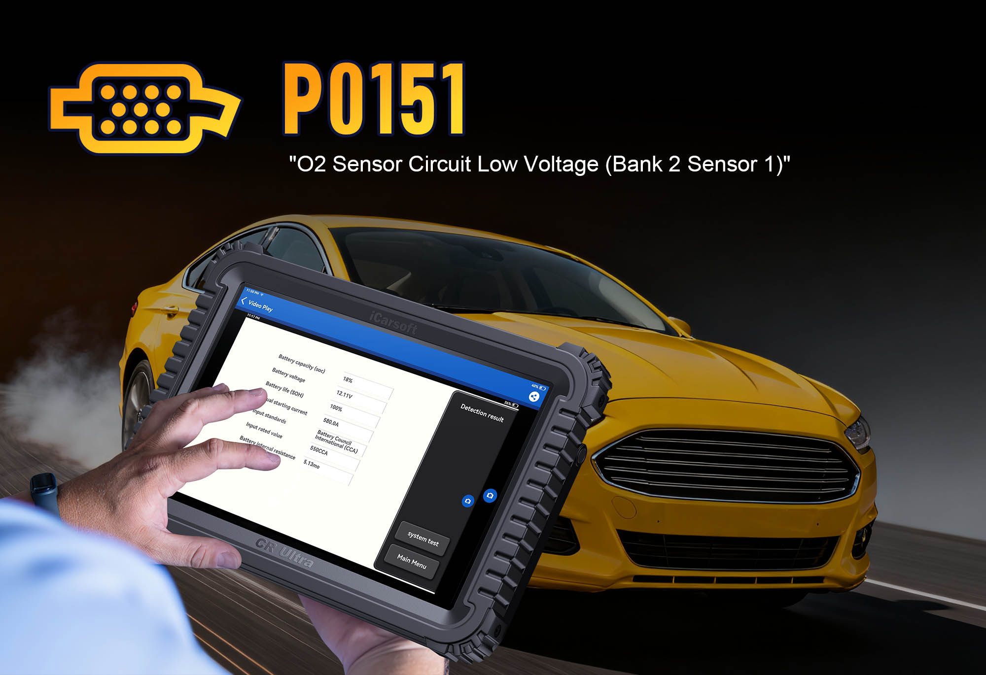 iCarsoft CR Ultra: Analyzing Bank 1, Sensor 1 O2 voltage to resolve P0151 low voltage issues
Understanding P0151: Causes & Key Symptoms
A low voltage signal from the Bank 1, Sensor 1 O2 sensor disrupts fuel control, leading to distinct performance issues rooted in an unstable air-fuel mixture. Below are the critical symptoms to identify and common causes to target.
Key Symptoms of P0151
-
Check Engine Light: Illuminates when the O2 sensor voltage remains below 0.45V for 10+ seconds during normal operation (varies by manufacturer).
-
Poor Fuel Economy: The ECM enriches the fuel mixture to compensate for the "lean" signal, increasing fuel consumption by 10–15%.
-
Rough Idle or Misfires: An unstable air-fuel mixture in Bank 1 causes uneven combustion, noticeable at idle or low speeds.
-
Hesitation During Acceleration: A lean condition limits power output, leading to delayed response when pressing the gas pedal.
-
Catalytic Converter Overheating: Unburned fuel from over-enrichment can ignite in the converter, raising temperatures and risking premature failure.
-
Cold-Start Issues: Lean conditions worsen in cold weather, making it harder for the engine to start or run smoothly until warmed up.
Common Causes of P0151
-
Faulty O2 Sensor: A worn, contaminated (oil/carbon), or damaged upstream sensor (Bank 1, Sensor 1) fails to generate proper voltage, stuck in a low range.
-
Wiring or Connector Issues: Corroded terminals, frayed wires, or loose plugs in the sensor circuit create high resistance, dropping voltage.
-
Vacuum Leaks: Unmetered air entering the intake manifold (via cracked hoses, loose gaskets, or a faulty PCV valve) creates a lean condition.
-
Fuel System Problems: Clogged fuel injectors, low fuel pressure, or a failing fuel pump restrict fuel delivery to Bank 1, causing a lean mixture.
-
Exhaust Leaks: Leaks before the O2 sensor draw in outside air, increasing oxygen levels in the exhaust and lowering sensor voltage.
-
MAF Sensor Malfunction: A dirty or faulty Mass Air Flow sensor underreports airflow, leading the ECM to supply insufficient fuel.
Why iCarsoft CR Ultra Excels at Diagnosing P0151
The CR Ultra outperforms basic tools with specialized features for O2 sensor and fuel system diagnostics, ensuring you don’t just "detect low voltage"—but distinguish between sensor faults and actual lean conditions.
O2 Sensor Waveform Analysis
Captures real-time voltage patterns of the Bank 1, Sensor 1 O2 sensor, identifying "flatlining" below 0.45V—confirming a low-voltage issue. Distinguishes between sensor failure (no fluctuation) and actual lean conditions (occasional low spikes).
Live Data Correlation
Cross-references O2 sensor voltage with fuel trim values, MAF readings, and fuel pressure. Positive STFT/LTFT + low voltage = actual lean condition; normal trim + low voltage = sensor fault.
Sensor Resistance Testing
Measures the O2 sensor’s internal resistance to verify functionality. Normal = 10–40 ohms (varies by sensor); infinite/erratic readings = faulty sensor (no guesswork on replacement).
3D Component Mapping
Displays high-resolution diagrams of the Bank 1, Sensor 1 O2 sensor, wiring harness, intake manifold, and fuel injectors for 200+ vehicle brands. Simplifies locating parts and leak points.
Vacuum Leak Detection
Integrates with smoke testing to pinpoint air leaks in the intake system (e.g., cracked hoses, loose gaskets) that cause lean conditions. Marks leak locations on the tool’s 3D map.
Fuel Pressure & Injector Tests
Verifies fuel delivery to Bank 1 (e.g., "Clogged injector 1—restricting fuel") and measures pressure to rule out pump/filter faults. Ensures you don’t replace a sensor for a fuel system issue.
Step-by-Step: Diagnose P0151 with iCarsoft CR Ultra
-
Connect & Confirm the Code
Plug the CR Ultra into your vehicle’s OBD-II port (use included adaptors for older models with non-standard ports). Power on the tool and select your vehicle via Auto VIN Scan (instant VIN reading) or manual entry (make/model/year/engine).
Navigate to Engine > Fault Codes > Read Codes to confirm P0151. Tap Code Details for vehicle-specific insights (e.g., "BMW: Bank 1, Sensor 1 O2 Voltage = 0.32V; Check Sensor & Intake Gaskets").
-
Locate Bank 1, Sensor 1 O2 Sensor & Related Components
Use the CR Ultra’s 3D mapping to avoid misidentifying critical parts (oxygen sensor positions vary by engine):
-
Go to Component Location > Engine > Exhaust System > O2 Sensors (Bank 1).
-
The tool displays a 3D diagram highlighting:
-
Upstream O2 Sensor (Bank 1, Sensor 1): Positioned before the catalytic converter on the cylinder bank containing cylinder 1 (marked with "B1S1").
-
Wiring Harness: Path from the sensor to the ECM, often routed near hot exhaust components (check for heat damage).
-
Intake Manifold (Bank 1): Common source of vacuum leaks (gaskets, PCV hoses, throttle body).
-
Fuel Injectors (Bank 1): Mounted on the cylinder head (clogged injectors cause lean conditions).
-
Analyze O2 Sensor Voltage & Fuel Trim Data
Real-time data reveals the severity and source of the low-voltage issue—follow these steps:
-
Start the engine and let it reach operating temperature (10–15 minutes) to ensure stable sensor readings.
-
In the CR Ultra, go to Engine > Live Data > O2 Sensors & Fuel Trim > Bank 1 and monitor four key parameters:
-
O2 Sensor Voltage (Bank 1, Sensor 1): Normal = fluctuates 0.1–0.9V. P0151 = steady <0.45V (e.g., "0.28V—persistently low, no rich spikes").
-
Short-Term Fuel Trim (STFT): Positive values (+10% to +20%) indicate the ECM is adding fuel to compensate for a lean condition.
-
Long-Term Fuel Trim (LTFT): Persistently positive values (+8% to +18%) confirm a chronic lean issue in Bank 1 (not a temporary fluctuation).
-
MAF Airflow: Low readings at idle (e.g., <2 g/s) = MAF sensor fault; abnormally high readings (e.g., >6 g/s) = possible vacuum leak.
-
Test O2 Sensor Functionality
A faulty sensor is the top cause of P0151—verify with the CR Ultra’s precision testing:
-
Waveform Test: Navigate to Special Functions > Engine > Sensor Tests > O2 Sensor Waveform (Bank 1, Sensor 1). The tool displays voltage fluctuations in real time:
-
Healthy sensor: Sharp transitions between lean (<0.45V) and rich (>0.45V) ranges.
-
Faulty sensor: Flat line below 0.45V (no rich spikes) or erratic, unresponsive voltage = replace sensor.
-
Resistance Test: Turn off the engine and disconnect the O2 sensor connector (use the tool’s safety guide for hot exhaust components). Use the CR Ultra’s Multimeter Function to measure resistance across the sensor’s signal pins (refer to the tool’s pinout guide). Normal = 10–40 ohms (check manufacturer specs). Infinite or erratic readings = faulty sensor.
-
Inspect Wiring, Exhaust Leaks & Vacuum Leaks
Physical faults (wiring damage, leaks) often mimic sensor issues—use the CR Ultra to guide your inspection:
-
Wiring & Connector Inspection: Follow the tool’s 3D wiring map to trace the harness from the sensor to the ECM. Look for:
-
Frayed wires touching the exhaust manifold (heat damage, causes short circuits).
-
Corroded connector terminals (white/green deposits) creating high resistance.
-
Loose or broken pins in the sensor plug (common after repeated disconnections).
-
Exhaust Leak Check: Use the CR Ultra’s Exhaust Smoke Test (under "Special Functions"). Connect a smoke machine to the exhaust manifold—leaks before the O2 sensor will release smoke, drawing in outside air and lowering sensor voltage. Focus on exhaust manifold gaskets and pipe joints near the sensor.
-
Vacuum Leak Detection: Run the Intake Smoke Test (under "Special Functions") to check for unmetered air entering Bank 1’s intake system. Smoke escaping from:
-
Cracked PCV hoses or faulty PCV valve.
-
Loose or damaged intake manifold gaskets.
-
Throttle body gasket or vacuum lines attached to the manifold.
= Vacuum leak (causes lean condition, trigger P0151).
-
Diagnose Fuel System & MAF Sensor Issues
Insufficient fuel delivery or a faulty MAF sensor can create a lean condition—rule them out with the CR Ultra:
-
Fuel Pressure Test: Go to Special Functions > Engine > Fuel System > Pressure Test (Idle). Normal pressure = 40–50 psi (varies by vehicle). Low pressure (<35 psi) = failing fuel pump or clogged fuel filter (restricts fuel to Bank 1).
-
Injector Balance Test: Select Injector Tests > Balance (Bank 1). The tool temporarily disables each injector to measure power loss. A larger drop in power for one injector (e.g., "Injector 3: -15% power loss") = clogged injector (restricts fuel flow, causes lean condition).
-
MAF Sensor Validation: Test the MAF sensor with Special Functions > Engine > Sensor Tests > MAF Accuracy. The tool compares real-time readings to expected values (e.g., "3.5 g/s at idle—normal" vs. "1.9 g/s—faulty sensor"). A dirty MAF can be cleaned with MAF cleaner; persistent issues = replace.
-
Repair & Clear P0151
Fix the root cause based on diagnostic findings (prioritize high-probability issues first):
-
Replace the Bank 1, Sensor 1 O2 sensor with an OEM part (use the CR Ultra’s Part Lookup for vehicle-specific compatibility—aftermarket sensors may have incorrect voltage ranges).
-
Repair wiring faults: Replace damaged wires with heat-shrink connectors (critical for wires near exhaust); clean corroded connectors with electrical contact cleaner or replace if pins are bent.
-
Fix vacuum leaks: Replace cracked hoses, loose gaskets, or a faulty PCV valve (follow the tool’s Repair Guide for torque specs).
-
Service the fuel system: Replace the fuel filter, clean clogged injectors with specialized cleaner, or repair low pressure (replace fuel pump if tests confirm failure).
-
Repair exhaust leaks: Replace worn gaskets or weld small holes in the exhaust pipe (use high-temperature sealant for minor gaps).
-
Clear the Code: In the CR Ultra, go to Engine > Fault Codes > Clear Codes to delete P0151.
-
Validate the Repair
Confirm the O2 sensor and air-fuel mixture are functioning correctly to prevent P0151 recurrence:
-
Recheck live data—Bank 1, Sensor 1 O2 voltage should fluctuate 0.1–0.9V, with STFT/LTFT returning to ±5% (normal range).
-
Test drive for 20–30 minutes, including:
-
Low-speed idle (500–800 RPM) to verify stability.
-
Acceleration from a stop to highway speeds (60–70 mph) to check for hesitation.
-
Cold restart (turn off engine, wait 10 minutes, restart) to ensure no cold-start issues.
-
Re-scan with the CR Ultra after 2–3 drive cycles: No P0151 recurrence = successful repair. For long-term confidence, run the O2 Sensor Stability Test (under "Special Functions")—the tool monitors voltage for 10 minutes and provides a "Pass/Fail" result.
Preventing P0151 Recurrence
The CR Ultra helps maintain reliable O2 sensor performance and fuel system balance long-term, reducing the risk of P0151 returning. Use these proactive features:
-
O2 Sensor Maintenance: Set the tool’s Service Reminder to replace upstream O2 sensors every 60,000–100,000 miles (sooner if the vehicle has high oil consumption—oil contaminates sensor elements).
-
Intake System Checks: Inspect vacuum hoses and intake gaskets quarterly (use the CR Ultra’s Visual Inspection Guide). Replace aging rubber components before they crack and cause leaks.
-
Fuel System Care: Add fuel system cleaner every 5,000 miles to prevent injector deposits; replace fuel filters annually (use the CR Ultra’s Fuel System Health Check to monitor pressure and injector performance).
-
Regular Scans: Use the CR Ultra’s Quick Scan monthly to monitor O2 sensor voltage and fuel trim. Catch "pre-code" issues (e.g., "Voltage occasionally drops to 0.40V") before they trigger P0151.
Conclusion: Precision for Low O2 Sensor Voltage Faults
P0151’s low O2 sensor voltage is a common but frustrating fault—one that basic scanners often misdiagnose as a "bad sensor" when the real issue is a vacuum leak or clogged injector. The iCarsoft CR Ultra eliminates this guesswork, guiding you to the root cause with OE-level tools like waveform analysis, leak detection, and fuel system testing.
For DIYers, this tool prevents costly misrepairs (e.g., replacing a $100 sensor when the fix is a $5 PCV valve). For professionals, it streamlines diagnostics and builds customer trust by fixing the problem right the first time. With the CR Ultra, resolving "O2 sensor low voltage" faults ensures your engine’s air-fuel mixture remains optimized—delivering better fuel economy, lower emissions, and reliable performance for every mile.