Diagnose & Clear P0120 with iCarsoft CR MAX BT: Fix Throttle Position Sensor Circuit Malfunction
Diagnose & Clear P0120 with iCarsoft CR MAX BT
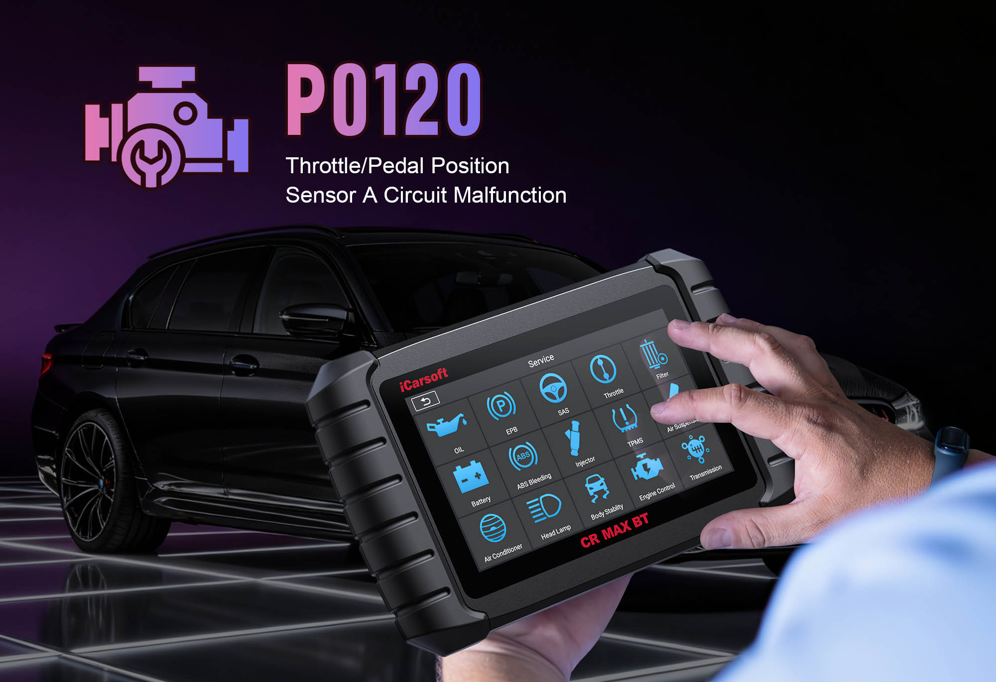
If your vehicle’s check engine light illuminates, you experience unresponsive acceleration, or it stalls unexpectedly, a diagnostic scan will likely return P0120. This OBD-II code stands for "Throttle Position Sensor (TPS) Circuit Malfunction"—a critical fault affecting the TPS, which monitors the throttle valve’s position to send real-time data to the Engine Control Module (ECM).
The ECM uses TPS data to adjust fuel injection, ignition timing, and idle speed. When the TPS circuit fails, the ECM loses accurate throttle position information, leading to erratic performance, reduced fuel efficiency, and safety risks. Basic scanners can’t isolate faults, but the iCarsoft CR MAX BT with specialized TPS diagnostics solves this. Let’s break down how to resolve P0120 step by step.
Understanding P0120: Symptoms & Causes
The TPS is mounted on the throttle body, linked to the throttle plate. It uses a variable resistor to convert mechanical movement to electrical signals: ~0.5V at idle (closed throttle) and ~4.5V at wide-open throttle (WOT). P0120 triggers when the ECM detects irregularities (no signal, erratic voltage, short/open circuit) preventing throttle position interpretation.
Key Symptoms of P0120
-
Illuminated Check Engine Light (CEL): A steady CEL turns on, and some vehicles display "Throttle System Warning" or "Reduced Power Mode" (limp mode).
-
Unresponsive Acceleration: Pressing the gas pedal leads to delayed or no power—dangerous for merging/passing.
-
Erratic Idle: Engine idles too high (1,500+ RPM) or too low (stalls at stops), especially in neutral.
-
Stalling: Engine cuts out unexpectedly, often when slowing down or stopping.
-
Poor Fuel Economy: Incorrect throttle data causes rich fuel mixture, dropping mileage by 15–25%.
-
Limp Mode Activation: Many vehicles cap speed at 40–50 mph to limit engine stress—requires code reset to restore normal operation.
Common Causes of P0120
|
Cause
|
Description
|
|
Faulty TPS
|
Internal wear (e.g., worn potentiometer contacts) causes erratic voltage or complete signal loss.
|
|
Damaged TPS Circuit Wiring
|
Frayed wires, rodent chew marks, or corrosion in power/ground/signal lines create shorts or open circuits.
|
|
Loose/Corroded TPS Connector
|
The sensor’s 3–4 pin connector (on throttle body) becomes loose, rusted, or dirty—disrupting electrical flow.
|
|
Throttle Body Carbon Buildup
|
Excess carbon sticks the throttle plate, preventing TPS from registering movement (common in vehicles >50,000 miles).
|
|
Blown TPS Fuse
|
A dedicated "TPS" or "Sensor Power" fuse in the under-hood box blows, cutting power to the sensor circuit.
|
|
ECM Malfunction
|
Rarely, the ECM’s internal TPS signal processing circuit fails—misinterpreting or ignoring sensor data.
|
Why iCarsoft CR MAX BT Excels at Diagnosing P0120
The CR MAX BT outperforms basic tools with features tailored to TPS circuit diagnostics—critical for safety and efficiency. Here’s its key value:
Wireless Bluetooth Connectivity
Test the TPS (tight engine bay spaces) from up to 30 feet away—no cords hinder access or risk wire damage.
Live TPS Voltage & Position Tracking
Monitors real-time voltage (0.5V–4.5V) and position (0%–100%), instantly flagging irregularities like stuck signals.
Bi-Directional TPS Calibration
Sends direct commands to test TPS response and calibrate to ECM—essential for post-repair alignment (45+ makes supported).
Circuit Integrity Checks
Identifies open circuits, shorts, or high resistance in wiring—pinpoints faults like frayed wires without guesswork.
Throttle Body Cleaning Reminder
Links TPS issues to carbon buildup (based on mileage), prompting maintenance to avoid mimic faults.
Step-by-Step: Diagnose & Clear P0120 with iCarsoft CR MAX BT
-
Initial Safety Check & Visual Inspection
1. Disconnect battery (optional): Remove negative terminal to prevent shorts; reconnect after 5 minutes to reset ECM.
2. Locate TPS: Use Component Location > Engine > Throttle System > TPS (bolted to throttle body near air intake).
3. Inspect connector: Disconnect (gloves if warm), check corrosion/bent pins—clean with contact cleaner, apply dielectric grease.
4. Inspect wiring: Follow harness to ECM, check frays/heat damage—repair with heat-shrink; replace if severe.
5. Check TPS fuse: Use Fuse Guide to locate/test—replace with same amperage (5A/10A) if blown.
6. Inspect throttle body: Remove air intake hose—look for black carbon buildup on the plate (note for later cleaning).
-
Connect the Tool & Confirm P0120
Plug CR MAX BT into OBD-II port, power on, select AutoVIN Identify to retrieve specs. Navigate to Engine > Fault Codes > Read Codes to confirm P0120. Tap Code Details for vehicle-specific insights (e.g., "Honda Civic: TPS Circuit Malfunction; Expected 0.5–4.5V, Actual: No Signal"), and check related codes (e.g., P0121, P0122).
-
Monitor Live TPS Data
Reconnect battery (if disconnected), start engine, idle 5 minutes. Navigate to Engine > Live Data > Throttle Position Sensor:
- TPS Voltage: ~0.5V (idle) → ~4.5V (WOT); erratic spikes/flat lines = circuit fault.
- TPS Position (%): 0–5% (idle) → 90–100% (WOT); mismatch with pedal movement = sensor/mechanical issue.
- Pedal test: Slow press/release gas—voltage/position should change instantly; delays = faulty TPS/sticky plate.
-
Test TPS Circuit Integrity
Turn off engine, disconnect TPS connector:
1. Power wire test: Set multimeter to "DC Voltage"—touch power pin ("V+" in pinout) + ground. Ignition "ON" = 5V; 0V = blown fuse/broken wire.
2. Ground wire test: Set to "Ohms"—touch ground pin ("GND") + chassis ground. Normal = <1 ohm; >5 ohms = poor ground.
3. Signal wire test: Check continuity between signal pin and ECM (use wiring diagram)—no continuity = broken wire.
4. Short-circuit test: Check continuity between power/ground/signal pins—any continuity = short (repair wiring).
-
Test the TPS & Throttle Body
1. TPS bench test: Remove TPS (torque 6–8 ft-lbs per Component Removal Guide):
- Connect to connector (or jumper 5V power/ground).
- Manually rotate internal shaft—voltage should rise smoothly 0.5V→4.5V; erratic/no change = faulty sensor.
2. Throttle body cleaning (if buildup):
- Spray throttle body cleaner on soft cloth—wipe plate/bore (no brush to avoid scratches).
- Reinstall air intake, start engine—retest TPS data to check if fault resolves.
-
Repair & Clear P0120
- Blown fuse/buildup: Replace fuse with OEM-compatible one; clean throttle body (as above).
- Wiring/connector: Repair frays; clean connectors with dielectric grease; replace damaged harness.
- Faulty TPS: Replace with OEM-equivalent (use Part Lookup—e.g., Bosch 0280122024 for GM, Denso 22620-AA210 for Subaru); torque to specs.
- ECM malfunction: Consult dealer for reprogramming/replacement (last resort—confirm with ECM Communication Test).
Clear & calibrate: Go to Engine > Fault Codes > Clear Codes; then Special Functions > Engine > TPS Calibration (follow prompts to align TPS with ECM).
-
Validate the Repair
1. Monitor data: Confirm voltage 0.5V→4.5V (smooth transitions) and position matches pedal movement.
2. Test drive: Operate 30 minutes—check idle stability, responsive acceleration, no stalling/limp mode.
3. I/M Readiness Test: Run via OBDII Functions for emissions compliance.
4. Save report: Use History & Report to document fault, repairs, and post-repair data.
Preventing P0120 Recurrence
-
Regular TPS Checks: Use Service Reminder to test TPS every 30,000 miles—catch early wear before P0120 triggers.
-
Throttle Body Maintenance: Clean every 40,000–50,000 miles (per Maintenance Schedule) to prevent carbon buildup.
-
Wiring Protection: Inspect harness every 15,000 miles—use heat-resistant loom near hot engine parts.
-
Lifetime Free Updates: Use One-Key Upgrade (Wi-Fi) to add new TPS diagnostic features.
Conclusion
P0120’s TPS circuit malfunction threatens driving safety with unresponsive acceleration or stalling. The iCarsoft CR MAX BT simplifies diagnosis with wireless convenience, live tracking, and bi-directional calibration—ensuring you fix the root cause (sensor, wiring, or buildup) instead of guessing.
With global coverage and 40+ service functions, the CR MAX BT is a long-term investment in throttle control and reliability. Restore responsive acceleration, improve fuel efficiency, and drive with confidence—all with one professional-grade tool.